Attachments
NDFC

In NDFC, VRF and Network attachments can happen independently, i.e. create VRFs and attach them to leaf switches then create Networks and attach them to leaf switches. The workflow can also be combined as you are doing in this lab where the VRF is created, then the Networks associated to the VRF, and finally the Networks are deployed, inturn, deploying the VRF. All of this adhering to Cisco best practices.

You have staged your overlay tenant VRF and staged two host Networks associated to your overlay tenant VRF in the previous sections. It is now time to attach these constructs to the leaf switches that require it. This requirement in reality would come based on a design of how hosts, such as ESXi are connected to your leaf switches. There are two standalone Linux instances connected to your Site1-L1 and Site1-L2 switches on Ethernet1/5. This is the interface you used policy to configure as an access interface leaving the access VLAN undefined. An additional part of the attachment workflow is selecting an interface(s) for the networks to be deployed, whether that is an access or trunk interface. For this lab, you will select your Ethernet1/5 interface between your two leaf switches for each Network you previously created.

Step 1 - Edit Attachments of Networks

  1. Click on X
To begin, this part of the lab is going to have you actually navigate back to the Networks view to demonstrate another way to navigate to Network Attachments with a consolidated view by activating filters automatically. One of the goals of the lab is to demonstrate the various flexible ways you can navigate within NDFC and view the elements that make up your fabric.
  1. Ensure Networks in the top navigation bar is still selected and where you are currently working
  2. Click the checkbox for BlueNet1 and BlueNet2
  3. Click Actions
  4. Click Multi-Attach

Step 2 - Select Site1-L1 & Site1-L2 to Attach BlueNet1 and BlueNet2 Network

  1. Locate and click the checkbox for Site1-L1
  2. Click Next

Step 3 - Attach First Network to Site1-L1 Ethernet1/5 and Second Network to Site1-L2 Ethernet1/5

In the Edit Network Attachment - Site1 wizard:
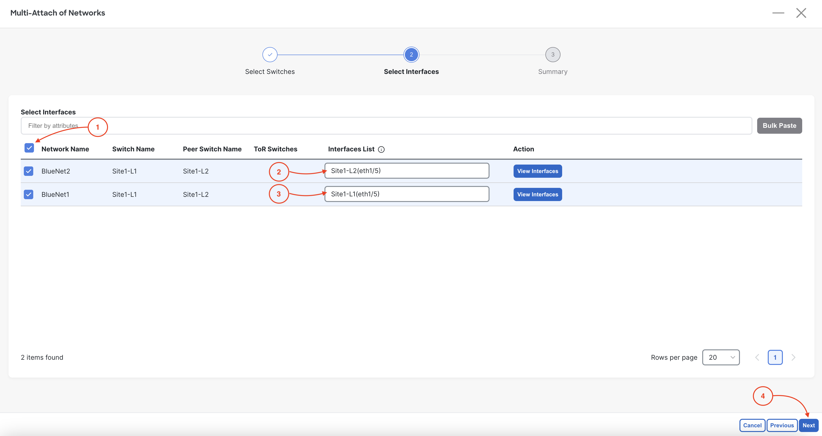
  1. Click the checkbox for BlueNet1 and BlueNet2
  2. Add Site1-L2(eth1/5) to the interface list of BlueNet2
  3. Add Site1-L1(eth1/5) to the interface list of BlueNet1
  4. Click Next

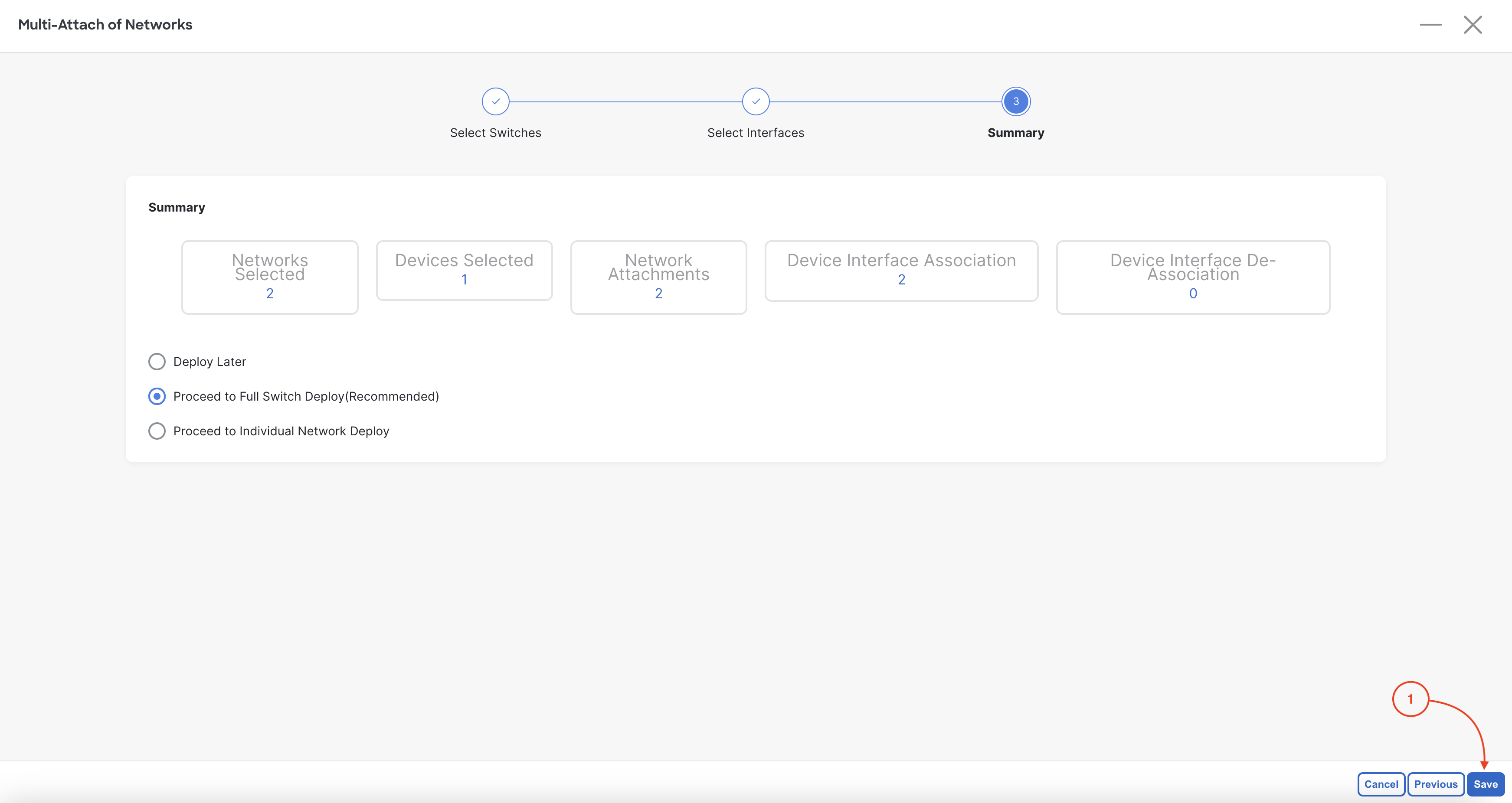
Step 4 - Proceed to Full Switch Deployment

  1. Click Save

Step 5 - Deploy Config for Network Attachments

  1. Click Deploy All

Step 6 - Confirm Networks Deployed

Confirm both BlueNet1 and BlueNet2 networks display as deployed:

  1. Click Close

Step 7 - Review Overview Dashboard

Revisit the main Overview dashboard to see the VRF and Network definition health displayed:

  1. Click Overview
  2. Locate the Networks/VRFs Definition


Continue to the next section to verify your Site1 Greenfield "Data Center VXLAN EVPN" fabric.